High-precision Modeling of Qatar Port Case Study
PROJECT SUMMARY
Client: A leading EPC Company
Location: Mesaieed, Qatar
Infrastructure Type: Port
BIM: Clove Technologies Pvt. Ltd.
Project: High-precision Modeling of Port
Project Commenced: April-2014
FINISHED: December-2017
Area: 26.5 sq. km.
Software Used: UAV & NavVis
Clove Technologies Pvt. Ltd., recently conclud-ed a Prestigious “High-precision Modeling of Port” Project using BIM. Creation of an Integrated Modeling and Shop drawings along with delivering High return on invest-ment on the project not only during the
construction stage but throughout the lifetime of the Asset forms the core ethos of a success-ful BIM Project,.
The Advanced Commercial Port Project spanning 26.5 Sq KM is a significant venture envisaged towards having a capacity of 7.5m containers per year once fully operational. The Port is scheduled to reach completion
by 2020.
" The Opening of the Port will now bring further food security and economic diversification in line with Qatar National Vision 2030, A Project that aims to boost the country’s economic diversity”
Jassim Bin Saif Ahmed Al Sulaiti, The Minister of Transport & Communica-tions, with media.
" Balancing Technology advancement along with environmental safety are our 2 core key concerns while building a Port. It is therefore critical to simulate the same at the design and modeling stage to avoid severe cost escalations. The project is a testimony of Model-Based Approach combining Digital Building Technolo-gy and Processes to promote the practice of efficient creation, management, and usage of documented data for building construction and operations while adding greater value to the establishment. The whole team was always on the same page in communicating the exact design intent to everyone (client, architects, suppliers, builders, environmental managers, etc) that is going to work on it. In addition to the above, Clove Technologies Pvt. Ltd., offered an extended BIM crew to the client, unifying a team of skilled draftsmen, modelers, and architects for the project.”

BIM IS NOT JUST A 3D CAD
BIM is essentially a value creating collaboration through the entire life-cycle of a property, reinforced by the creation, collation and exchange of shared 3d models and intelligent-structured data attached to them.
SCOPE OF WORK
Our Scope entailed Architecture, Structure and MEP & FP services Modeling and Coordination with the Design Documents, approved material submittals & Specifications Provided by Client on 3 Administration Buildings along with 2 Chiller Farms and 2 Substations
which are strategically located.
The scope of work in this project is to design elements, construction, commission-ing and handover of 3 buildings and associated infrastructure
including 2 Chiller Farms and 2 substations of total GFA around 33,832 m2.
THE SCOPE OF WORK THAT APPLIES TO THE PORT BUILDINGS INCLUDES BUT WAS NOT LIMITED TO THE MODELING AND SIMULATION OF THE FOLLOWING:
- Excavation and Earthwork
- Concrete work
- Brickwork & block-work
- Roofing
- Structural steelwork
- Metal Works
- Plumbing and Engineering installations
- Electrical Installations
- Plasterwork, floor, wall and ceiling finishes
- Painting and Decorating
- Drainage
- Passive / Active Fire and Life Safety Systems
- Building Management Systems
- Making connections to incoming utilities and outgoing service
OUR SOLUTION
- Created project scheduled model as per LOD 400 standards, comprising Project Plan, Estimation as well as Actual time details and the shared model was then hosted into the cloud, using NavisWorks. We created an Integrated Collaborative Environment which is very critical for forming Multi-Disciplinary Coordination Processes, providing Access to relevant personnel for accessing and contributing real-time data.
- Generated shop drawings incorporating complete fabrication and installation of all components, to be utilized by specific trade contractors and fabricators. Building elements are modeled as specific assem-blies with complete fabrication, compila-tion, installation and detailed reports in addition to precise quantity, size, shape, location, and orientation.
- In addition to actual and accurate in size; shape, location, quantity, orientation, as well as non-geometric information is attached to modeled elements in this field verified As-Built congregations. The elements of these representations are modeled as constructed assemblies to support maintenance and operations. They are made to demonstrate then-pres-ent circumstances and incorporate finished parameters as well as qualities point by point.
- The Project commenced with complete digitization of the primary design documents the customer had provided, followed by building 3D designs while keeping an eye on clashes and design conflicts.
- Construction documentation was done as per LOD 300 standards and a detailed clash report was presented along with design to the Architect. Clash-free designs of LOD 350 were created including upgraded designs that were proposed by us in the clash reports.
- Created bid-ready BIM models with accurate modeling and shop drawings to aid detailed estimation. Produced a graphical representation of model elements and details as a specific system, demonstrating their assembly in terms of size, shape, orientation and their interface with other elements of the building. The delivered documentation also included graphical depiction with non-graphical (written) definitions.
At every level of project progression, Modelling had been worked on Revit and Coordination between services was created in NavisWorks.
MAIN CHALLENGES AND RESOLUTIONS
Sloped roof conflicting with rooms & facade - Main Administration Building
The sloped steel roof of roof of the building was challenging the rest of the building design. Our strategic predictions showed that it would be highly complex while constructing the rooms and façade especially Mullions’ Placement and installation of Light Fixtures. During the design digitization, our team spotted and raised multiple clash reports with RFI’s which resulted an alteration in the primary design before the actual construction started.


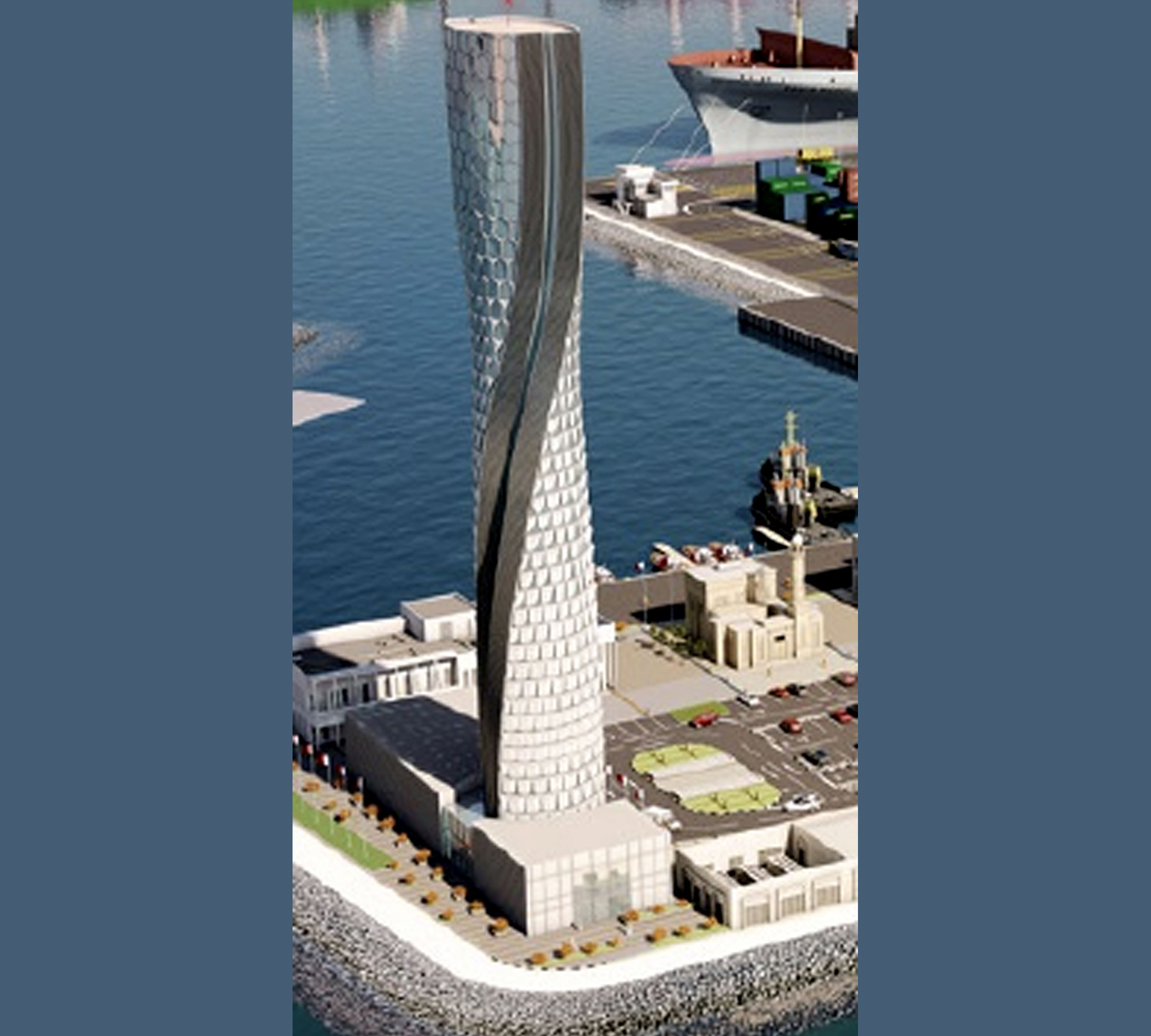
Complications with site amenities - Control Tower
Since the Control Tower Building was designed to be purpose-built in Helical Shape; Modelling Structural elements for areas like Lifts was complicated with MEP Services. Especially modeling & fabricating the crane supports through the assembly was causing damage for certain MEP configurations thus affecting the material cost and estimated time for the whole structure. Immediately creating a simulation model during the structural construction, showing the deviations of the exact work on the site, helped the architects to come up with an alternative structure for the site amenities to save the project from any unanticipated complications.
Pool taking too much space - Customs Administration Building
While creating design documentation, we realized that the pool, designed to be built in top floor was not leaving enough vertical space to the rooms on the floor beneath the pool. After trying to adjust various aspects and attempting design alterations, we realized that it was impossible to accom-modate enough room space to those chambers. The digital representation with detailed clash report made the designer re-think about the pool and finally the plan to construct a Pool was dropped and the floor was redesigned before the construction started.

HOW DID BIM HELP?
- Project warranted a seamless collaboration between MEP contractors and architects to meet the dual demands of increasing workload and scale. With our BIM enabled coordination system, most of the major challenges showed up during the planning and modeling stages, Improvements were carried out resulting in a smooth coordinated construction project.
- Inclusion of specific images/pictorial representa-tions in the clash reports provided better understanding thereby helping the designers to come up with improved alterations for each design conflict.
- Using BIM methodology, we were able to establish improved collaboration between teams especially while creating BoQ’s and schedules, which is very important while constructing such complex purpose-built projects.
- By providing high-quality virtual models, we enabled the stakeholders to visualize the exact design intent and take more informed decisions. Preparing and sharing room-wise and floor-wise coordination sheets at regular intervals or On Demand Basis improved the design and construc-tion synchronization.
- Raising detailed clash reports way before the actual construction helped the stakeholders save a great deal of time and money. Creating case simulations gave us power to show planned, estimated and actual construction sequence variations as well as its consequences.
- BIM enabled the client with better understanding on a real time basis and implement an effective design process. The information database connect-ed to each BIM element made the requirement and specification workflow easier.
Key Take Away:
Client was able to save time and money through coordinated design and effective construction practices.
